Jump:
 Objectives
 -
Concept -
Design -
Analysis -
Fabrication -
Assembly -
Testing -
Results -
Blog
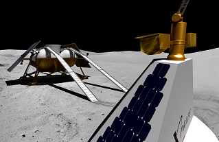
Astrobotic Tech, a Carnegie Mellon spinoff lead by Red Whittaker, is developing a robotic moon rover and lander to compete in the Google Lunar X Prize and establish a sustainable business selling payload delivery to the moon.
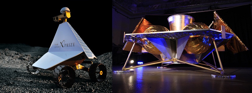
Photos: Astrobotic Technology, Inc.
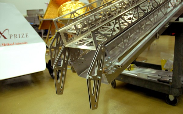
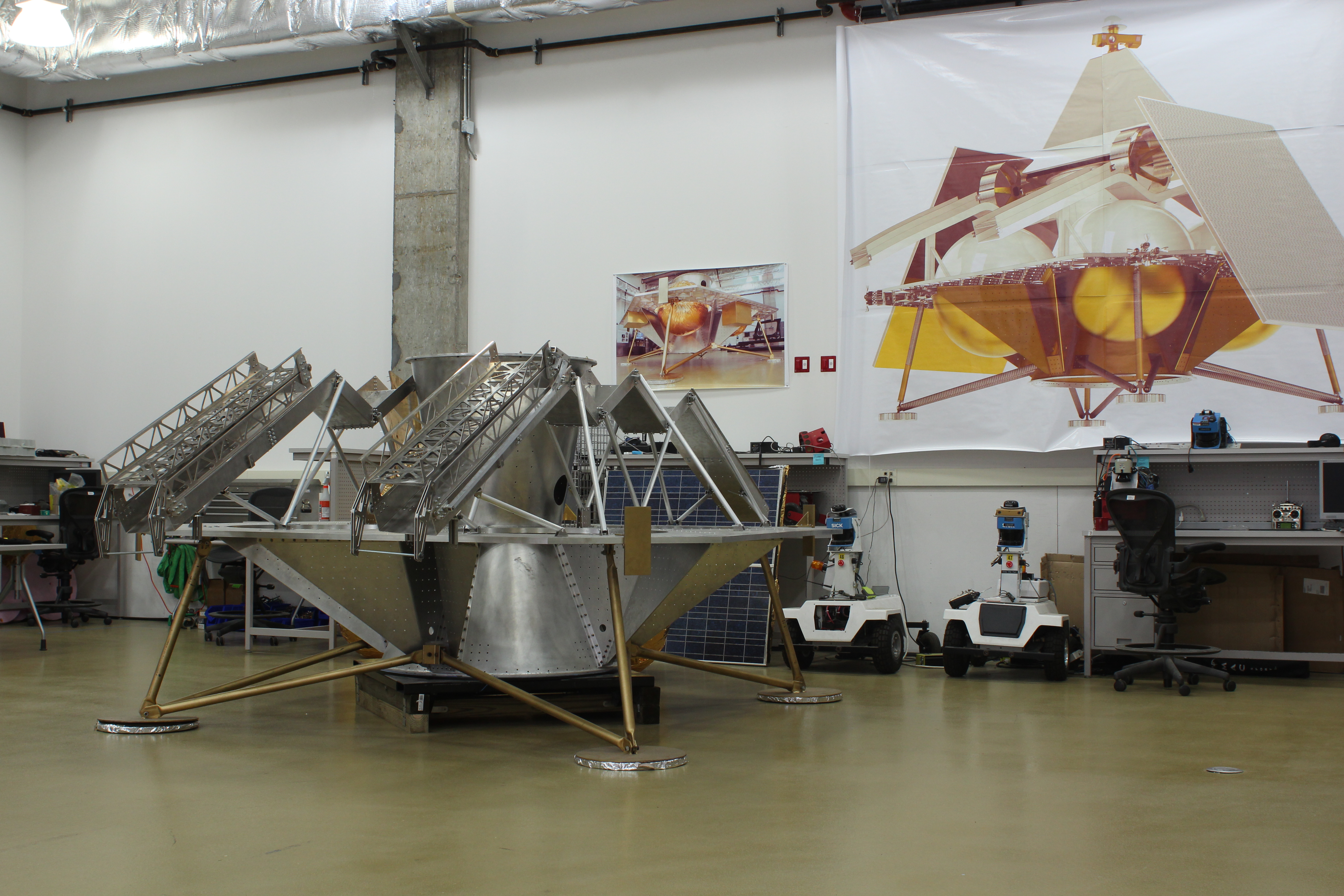
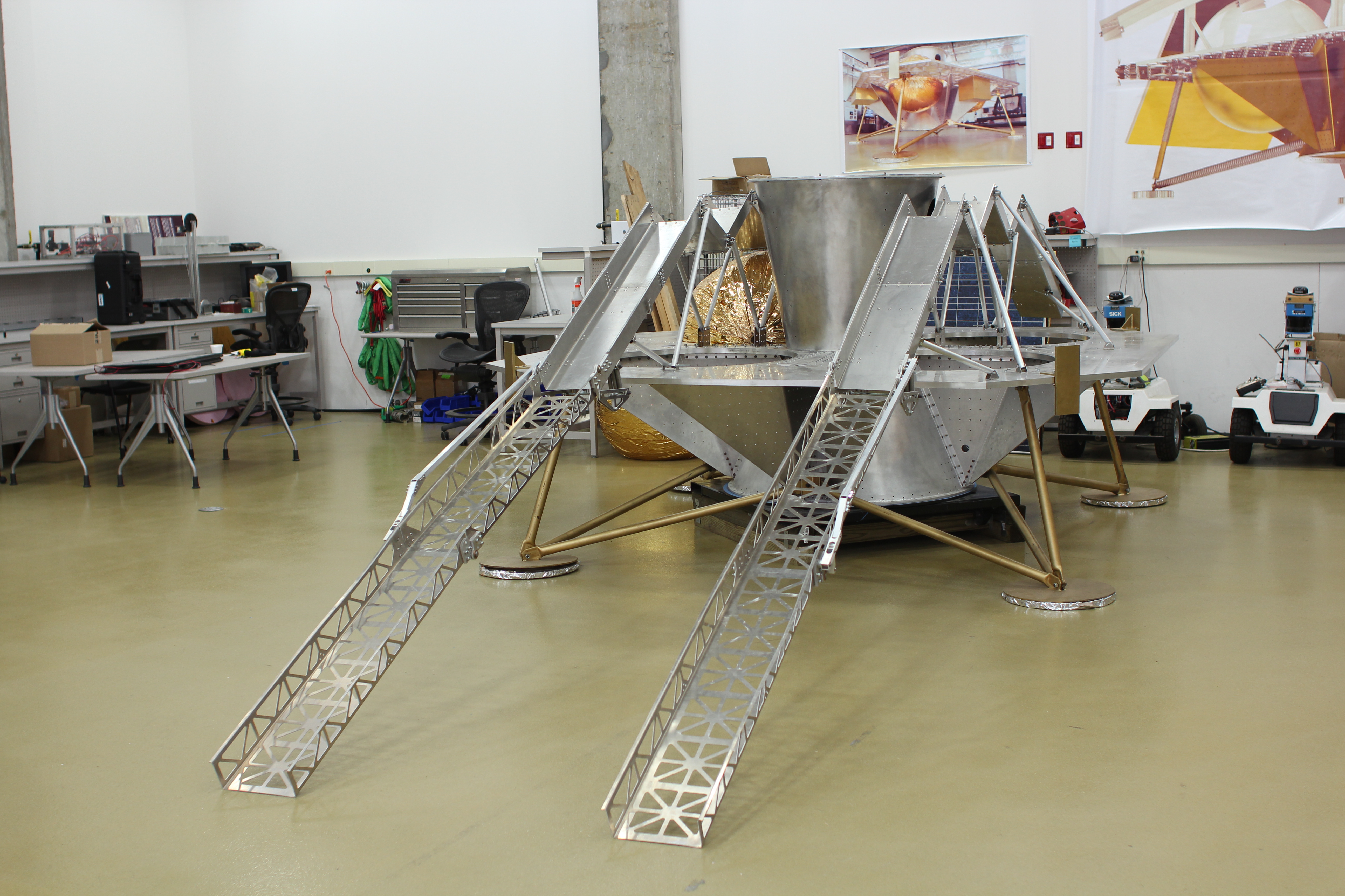
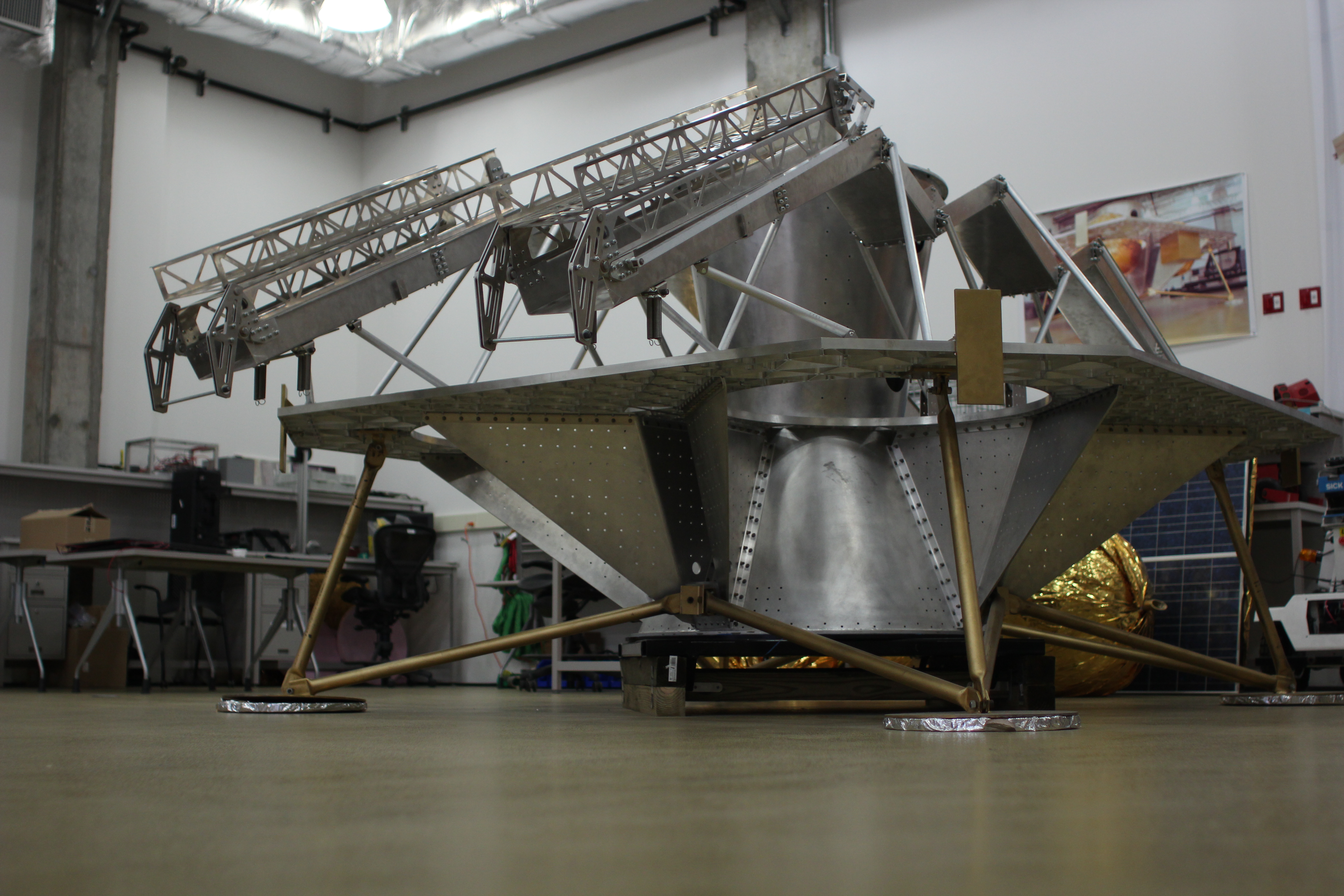
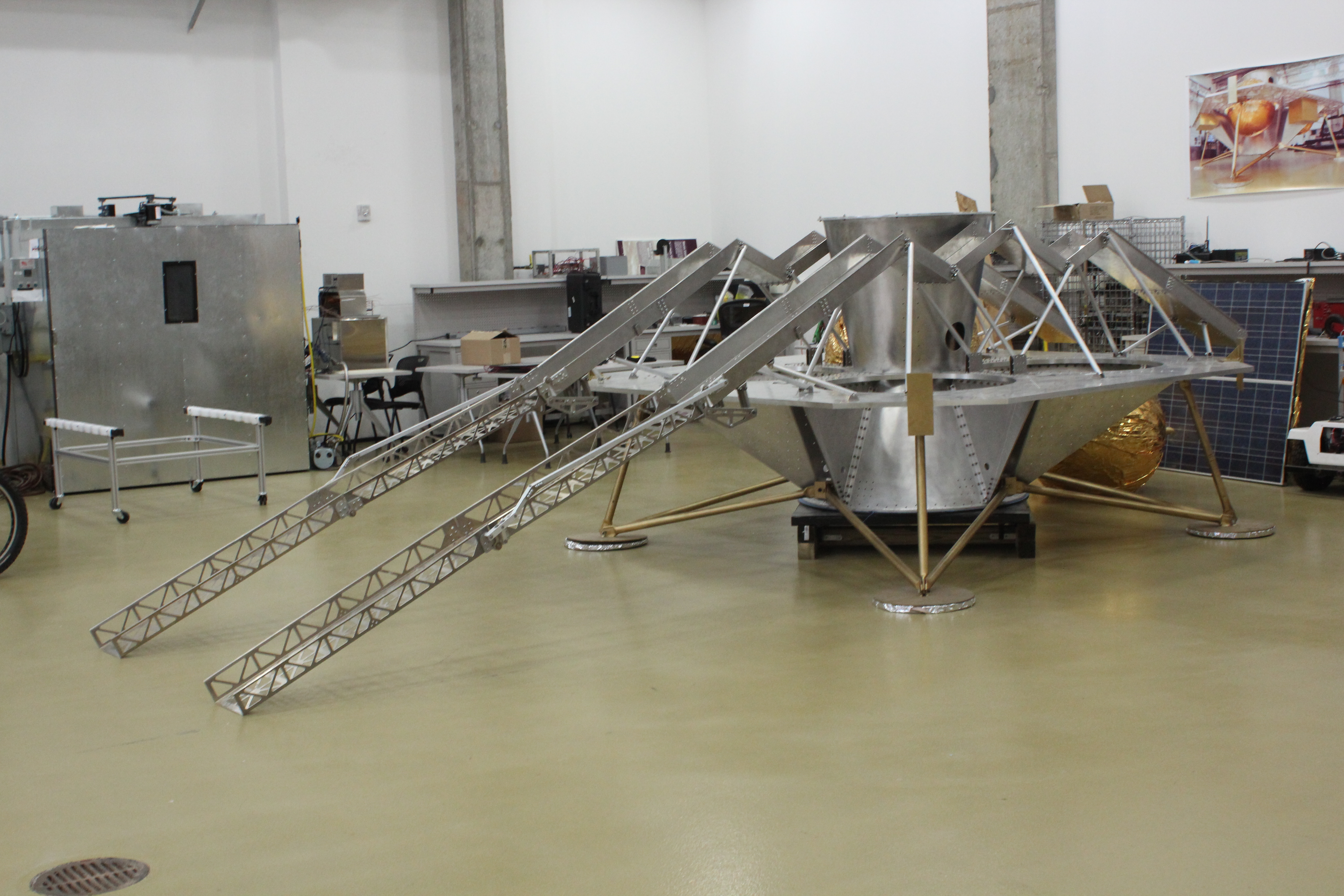
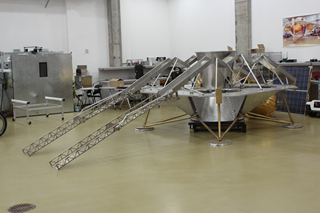
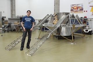
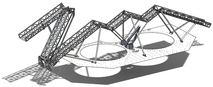
My contribution was a full-scale prototype deployable ramp system which the rover uses to egress from its position atop the lander onto the lunar surface. The pair of ramps are 20 feet long with over 350 machined components, designed and built in 4 months on a 3-person team.
The project was the focus of a graduate-level robotics course, working closely with the Planetary Robotics lab staff and their resources.

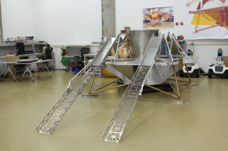
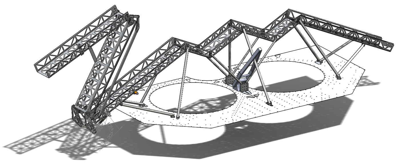
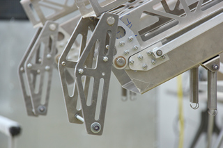
The main ramp channels carry the rover during launch and spaceflight, supported by a structural tubuing space frame. The zig-zag shape keeps the system more compact and lightweight, and the rover can drive off without contacting other lander parts.
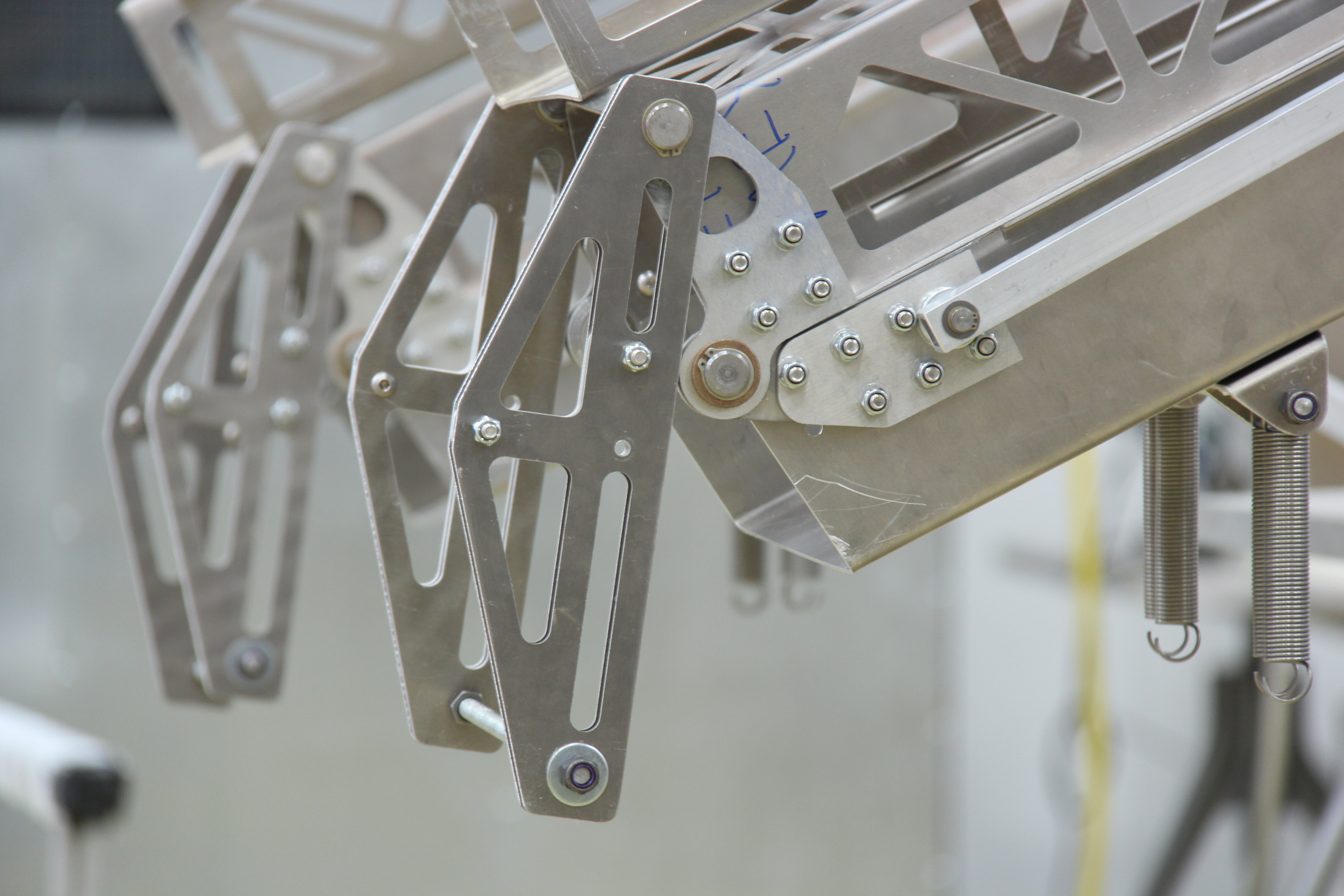
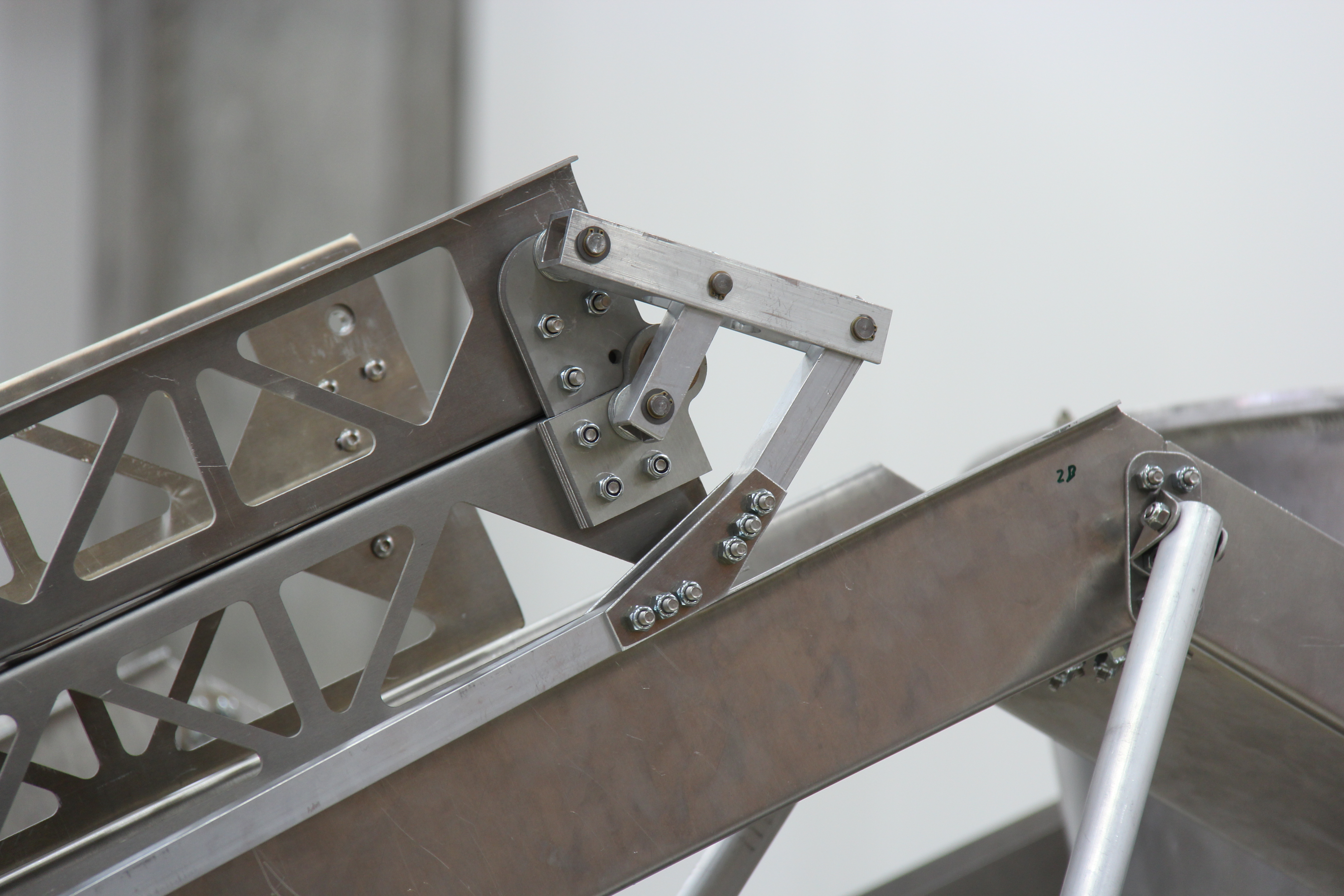
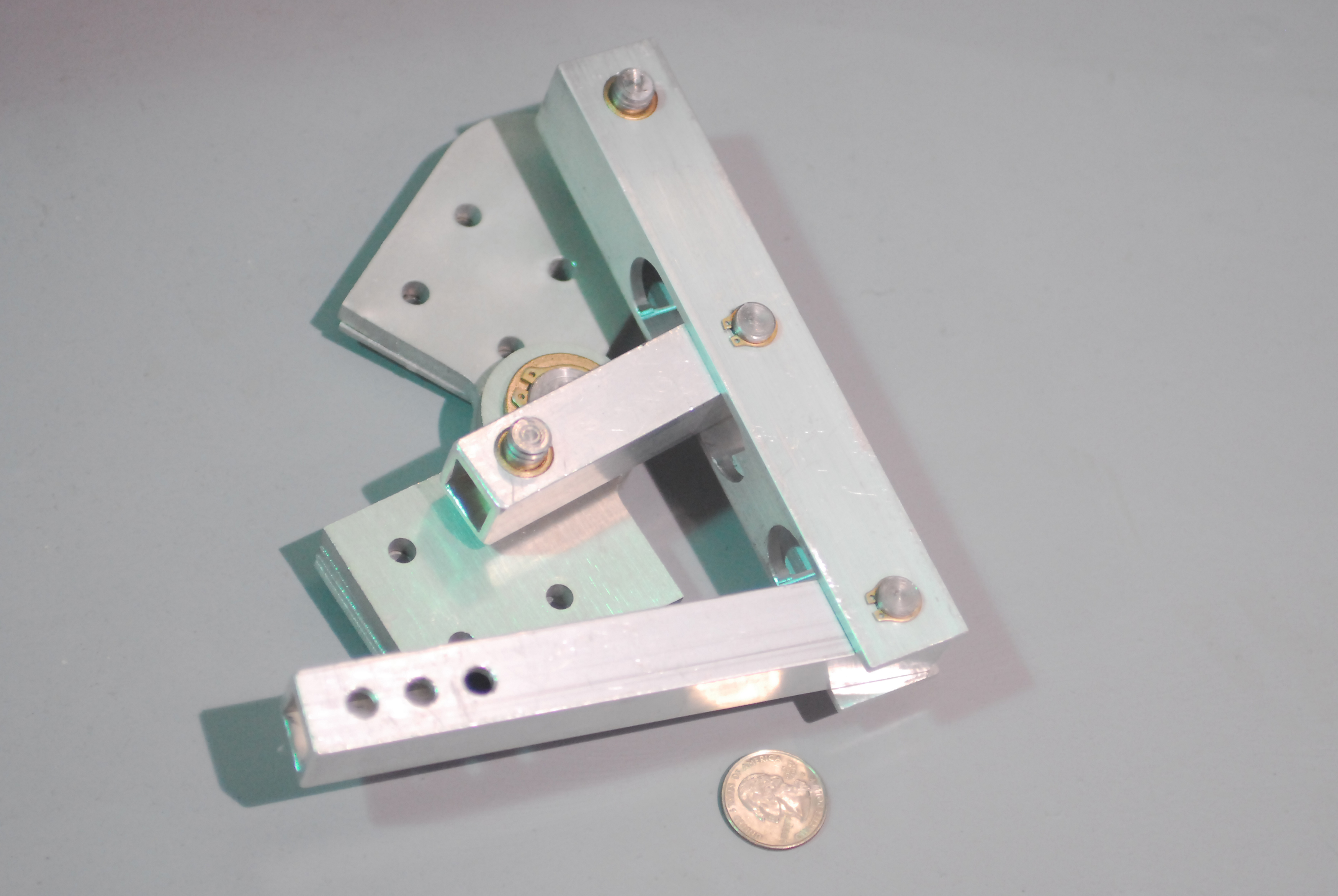
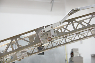
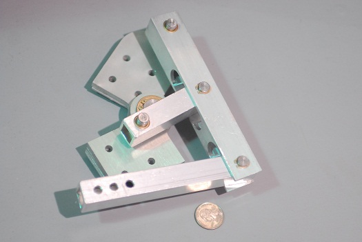
The ramps are spring-loaded and unfold when triggered. Hinge, linkage and release mechanisms were all designed for the purpose. The first hinge incorporates the springs release lever and four-bar linkage mount. When the ramp is released, the spring pulls open the first ramp segment and imparts enough inertia for deployment.
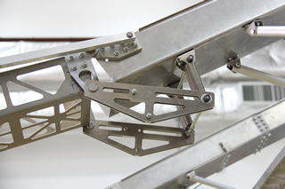
The second hinge incorporates linkage elements which pull open the second ramp segment during deployment.
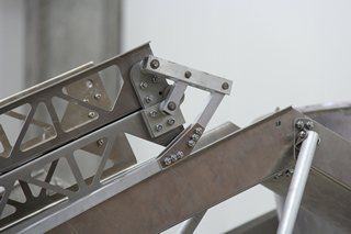
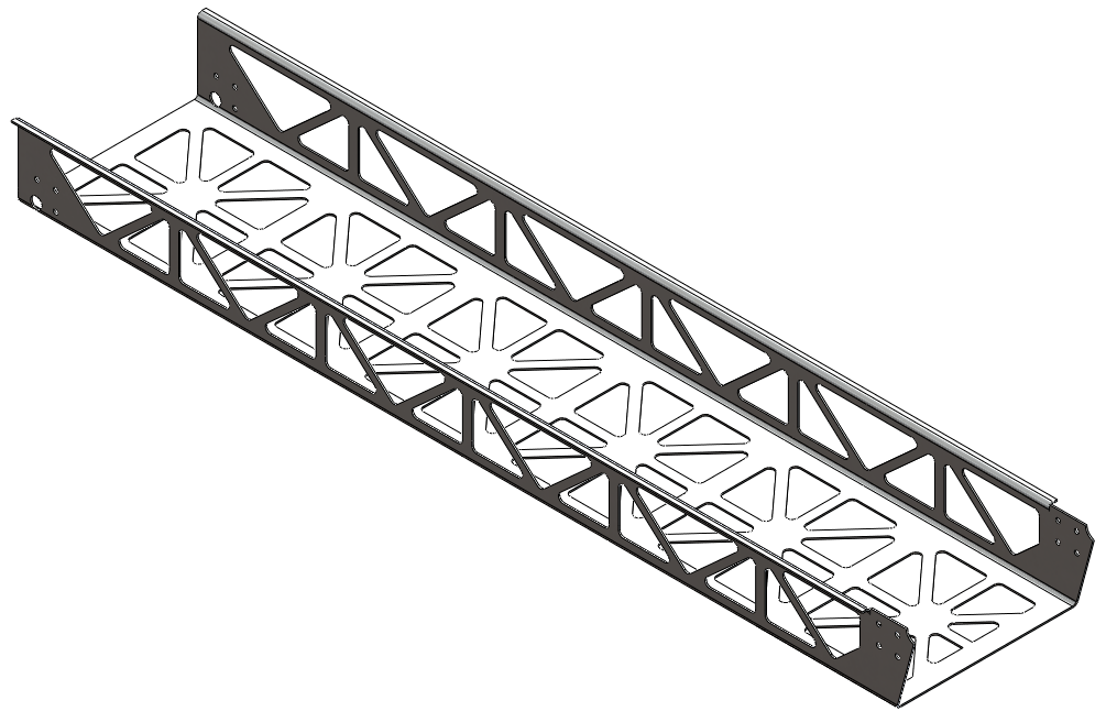
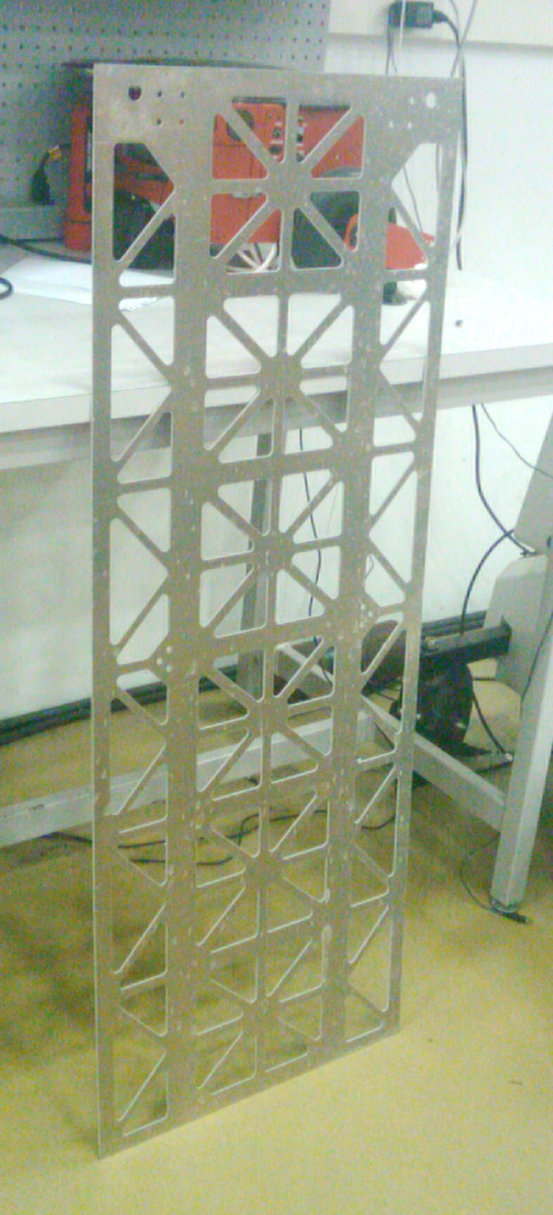
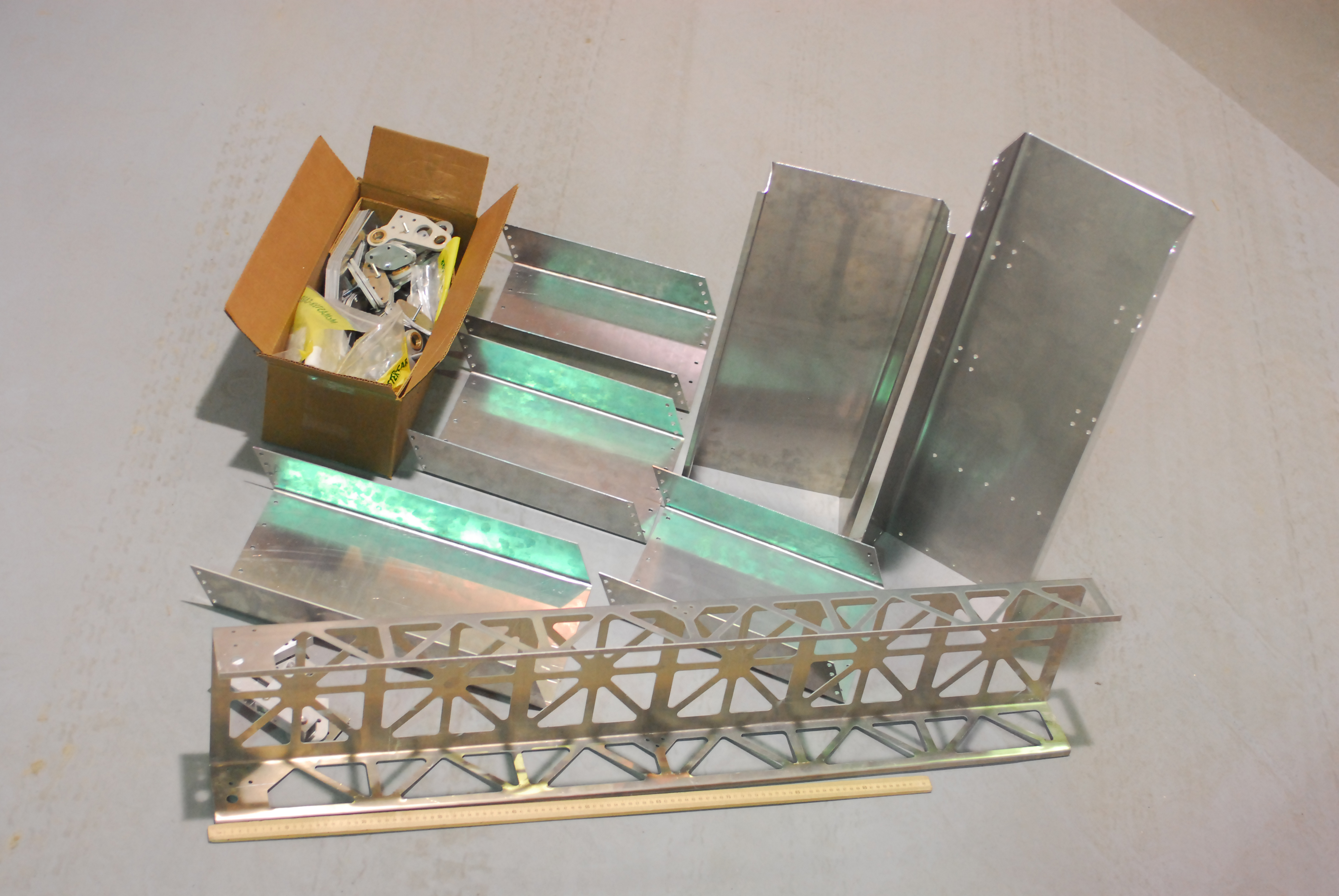
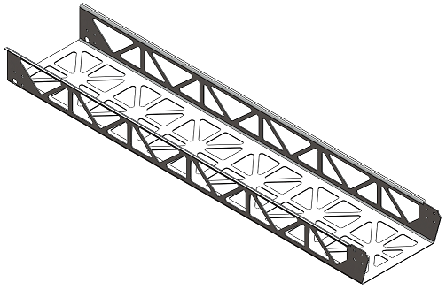
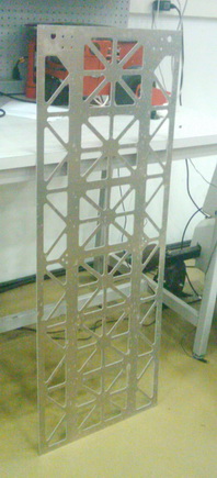
The deployed segments are made lightweight by cutting a folded aluminum sheet into a truss system. Stiffness is maintained using flanges, bends and diagonal members in the sheet metal.
Our prototype was built to:
- gain insight into the deployment kinematics
- test rover egress path geometry
- demonstrate lightweight construction within the mass budget
- prove feasibility of the folded sheet metal design
- convey visual impact (look recognizable and appropriate in photos)
Lastly, our project as a whole sought to produce CAD models and analysis results that could be used and modified by lab members in the future.
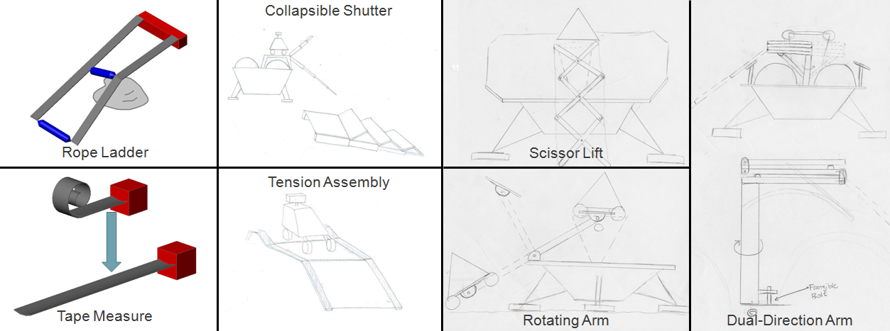
The first step was to figure out what our ramps would look like, and how we would build them. Much of this had already been narrowed down in the past few years, so we weren't starting from scratch. One of the challenges of the project was rapidly absorbing and internalizing three years' worth of design and research.
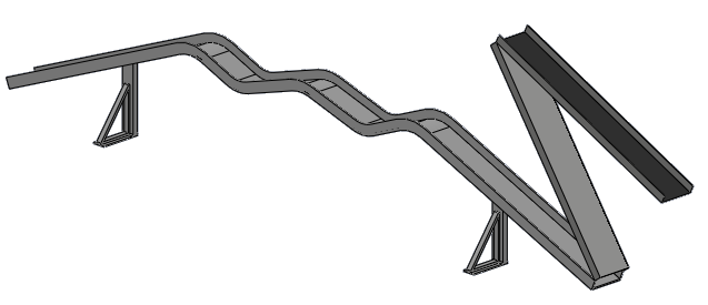
A pair of thin ramps having two egress options (rover drives forwards or backwards), with two segments that fold up or telescope for storage during flight.
The W-shape in the middle locks the rover wheels in place more securely to reduce vibration and movement during flight, as well as lifting the rover body clear of the central cone during egress. The shape also neatly avoids interference with the fuel tanks.
Nevertheless, we gave it the standard treatment to see if we could do one better.

A PUGH chart and other trade study tools helped guide the brainstorming. Besides the default configuration, we considered a "dual-direction" ramp which could rotate to deploy in either direction, potentially weighing half as much.
However, the added mission complexity proved to be its downfall. The default design deploys in two directions simultaneously, so any obstacles that would hamper egress are immediately obvious. The dual-direction ramp design requires obstacle evaluation even before the ramps are deployed, effectively making the same decision with less information. The idea was shelved.
Getting from concept to manufacturable design was a daunting challenge. Bent sheet metal would be our main ingredient, forming the main load-bearing segments and various features of the ramp system. The reasoning was that a U-channel beam would be well-behaved under load and its side walls would help guide the rover as it drove off.
To save on weight, we would water-jet-cut a truss pattern into the sheet metal before bending, leaving just enough metal to support the load without buckling.
A scalable CAD framework is developed which allows adjustment of dimensions on a global scale, propogating changes through all assembly parts while maintaining mechanism functionality.
Every dimension - thickness, cross-piece width, fillet radius, etc. - was run through an optimisation scheme in an attempt to maximize the strength-to-weight ratio while maintaining a reasonable safety factor.
Besides the main segments, many other sub-systems had to be designed: hinges, four-bar linkage, support structure, spring deployment mechanism, damping... each a potential project in its own right. We decided to design the sub-components for stiffness, making them heavier than they need to be but ensuring they would not be a weak link in the design. For a first prototype, this seemed acceptable.
The deployment mechanism uses springs to store energy all the way to the moon, where the energy is released when frangible bolts free the clamping mechanism, allowing the ramps to unfold.
Linear springs pull a pair of levers attached to the first segment, exerting a torque which causes the segment to unfold. While the spring pulls on the lever, it is effectively rigidly connected to the first segment. Somewhere past the half-way point, torque is no longer needed as gravity takes over the deployment process. Here, the springs are fully contracted and act as a rigid body, thus pushing on the lever and causing it to rotate with respect to the first segment.
This is where damping comes into play - a localized damper on the lever-segment hinge could slow the second half of the deployment to prevent a strong impact with the lunar surface, without impacting the first half of deployment when torque is needed.
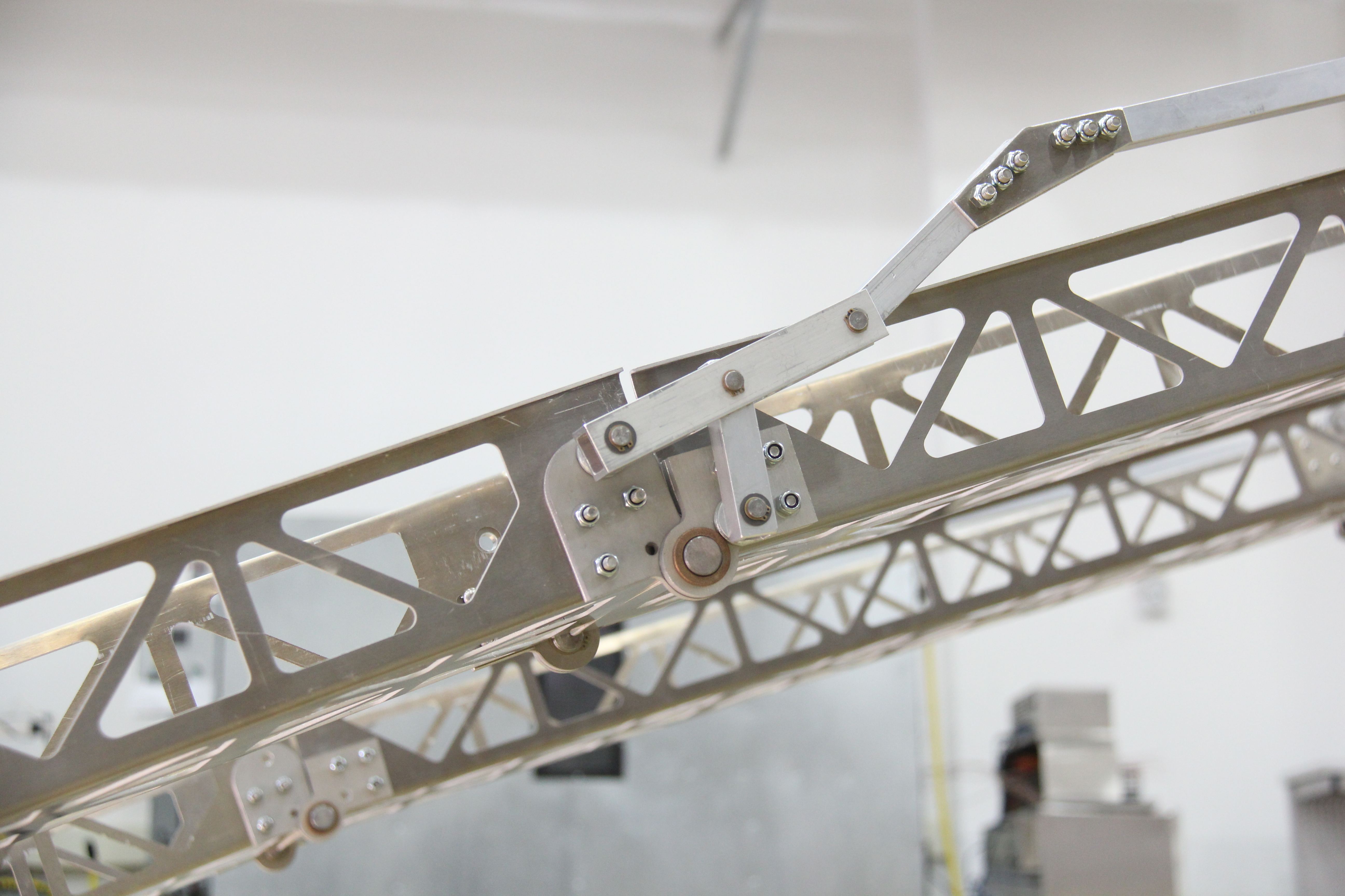
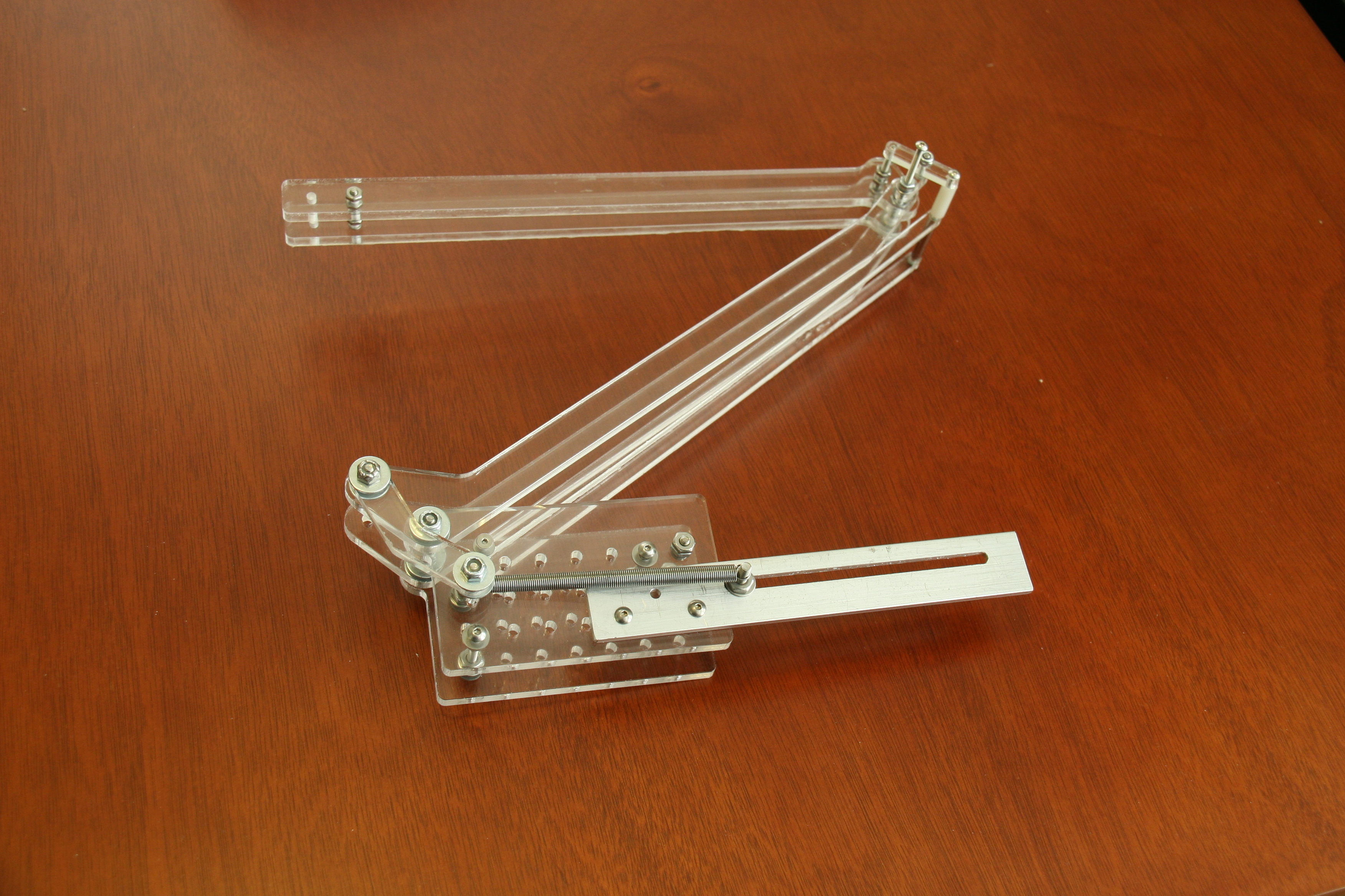
To open the second link, a four-bar linkage is designed and adapted for our ramp dimensions. To alleviate doubts that it would work, a small-scale prototype is built out of acrylic:
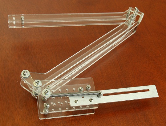
The full ramp deployment, acrylic prototype and scalable CAD framework demonstration can be seen here:
To determine proper dimensions for all ramp segments, we created a SolidWorks simulation which helped us minimize the egress angle while preventing the rover from colliding with the cone, and staying within our manufacturable limits (the cheaptest waterjet we got access to was 48"x48").
The problem was complicated by planned changes to the rover chassis; the next generation had much larger wheels, set much wider apart, so our design somehow had to accomodate both options. The solution was to design for the future, not yet built rover and accomodate the current design using temporary add-on parts.
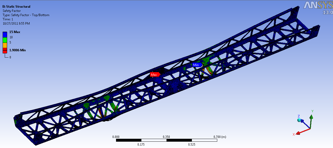
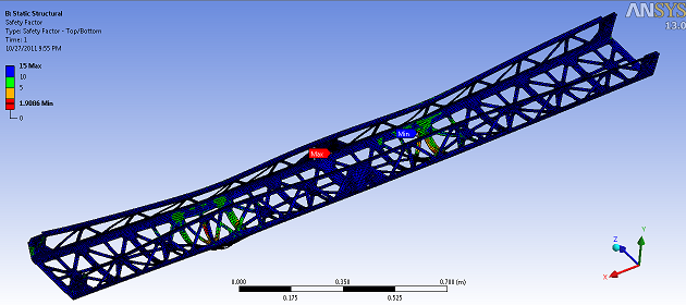
In parallel with our design efforts, we constantly checked its validity using ANSYS finite element analysis, hand calculations and various home-brewed numerical methods. One challenge was keeping the safety factor above 1.5:
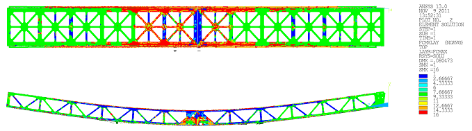
To calculate the moment profile on our simply-supported ramp segments, we wrote a script which used a numerical method to calculate the shear and moment experienced by the ramps as the rover rolls down them.
This suggested the use of a tapered ramp design, which we experimented with for a while, but eventually abandoned due to various geometry problems and sheet metal bending complications.
We also explored a possible carbon fiber & aluminum honeycomb composite design, and ran an ANSYS analysis using a custom script:
A composite design is ripe for exploration, and could be the next step in this project.
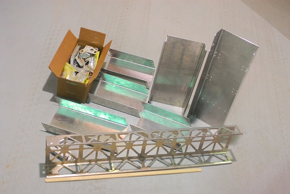
Much of the detailed machining was done using a Flow 4400 waterjet cutter at
NREC. As such, our design was heavy on "2.5D" elements - 3D shapes formed using slices of 2D profiles. Luckily my experience with laser-cut acrylic was applicable to water-jet aluminum.
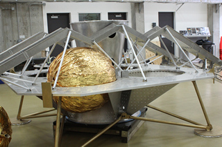
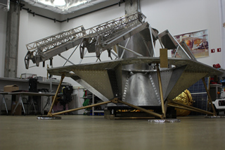
Note: photos #2, #3 & #4 by Guillermo Gomez
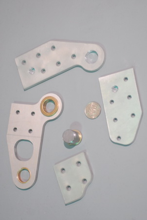
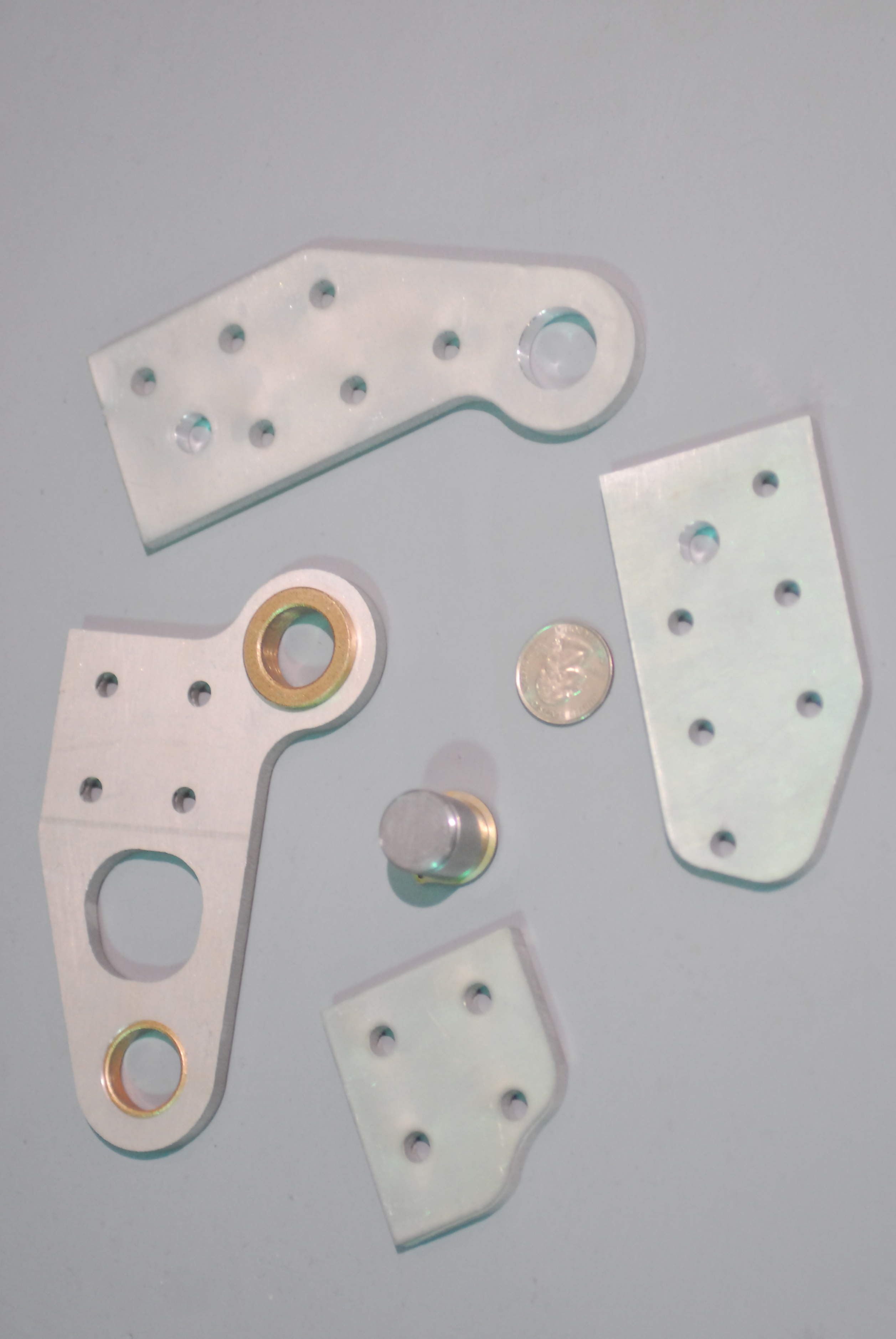
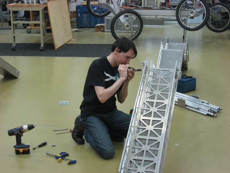
All components needed at least some additional machining, and of course not everything could be made from sheet metal. Here is part of the four-bar linkage connected to a hinge:
Due to budget limitations, all of the fixed segments had to be cut out by hand on a bandsaw instead of water-jet. This changed the appearance and drastically increased the weight labor required, but does not effect deployment testing. Some highly visible parts had their profiles cut with CNC for a more polished look.
An unexpected development during water jet cutting was de-lamination of our 0.08" thin aluminum sheets. This seems absurd considering aluminum is typically a homogenous, bulk material. However, we eventually determined the combination of material properties and manufacturing process that caused the phenomenon.
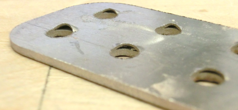
Since aluminum 5052 is cold-rolled, its outer surface is work-hardened and stronger than material on the inside of the metal sheet. Water-jet cutting comprises two operations: piercing (cutting a hole through a solid sheet) and cutting (removing material from the edge of an existing opening). While piercing, as the high pressure water jet reaches the hard outer surface on the opposite side, the weaker inner layers are the first to give way, allowing the outer layer to separate and form the domes seen in the photo. The solution is to locate pierce points as far away from the cutting edge as possible, and use a lower pressure during piercing lead-out.
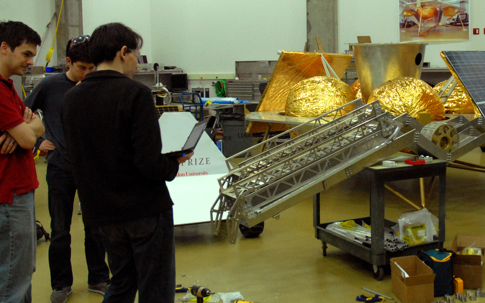
Once all the parts were machined, it was time to assemble our giant erector set. I made a time-lapse for the occasion:
It wasn't nearly as interesting as I'd hoped, since the assembly actually stretched out into days and weeks.
Everything was bolted together with mounting plates, to make potential disassembly easier. The large fixed W-shape ended up split into 8 large components due to manufacturing limitations, but in principle a carbon fibre version could be made as a single piece to save weight.
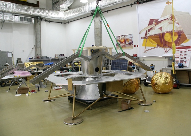
After some initial testing, we would attach the ramp segments to the lander by hoisting it on a crane and aligning everything with strings and a wooden jig representing the rover dimensions:
Here is our first deployment test, using springs to fully unfold the ramp segments:
In the end, the main focus became deployment: our design worked consistently and reliably, and gave rise to a solution to the semester-long question of damping.
Rover egress geometry remains to be tested - the question of future vs. current rover wheel size will be solved by inserting temporary platforms into the W-shape. Traction will be solved with adhesive-backed friction pads, coating or a silicone bed.
Visual impact was certainly achieved. Due to budget limitations the entire ramp assembly could not be water-jet, but the result is better than we expected.

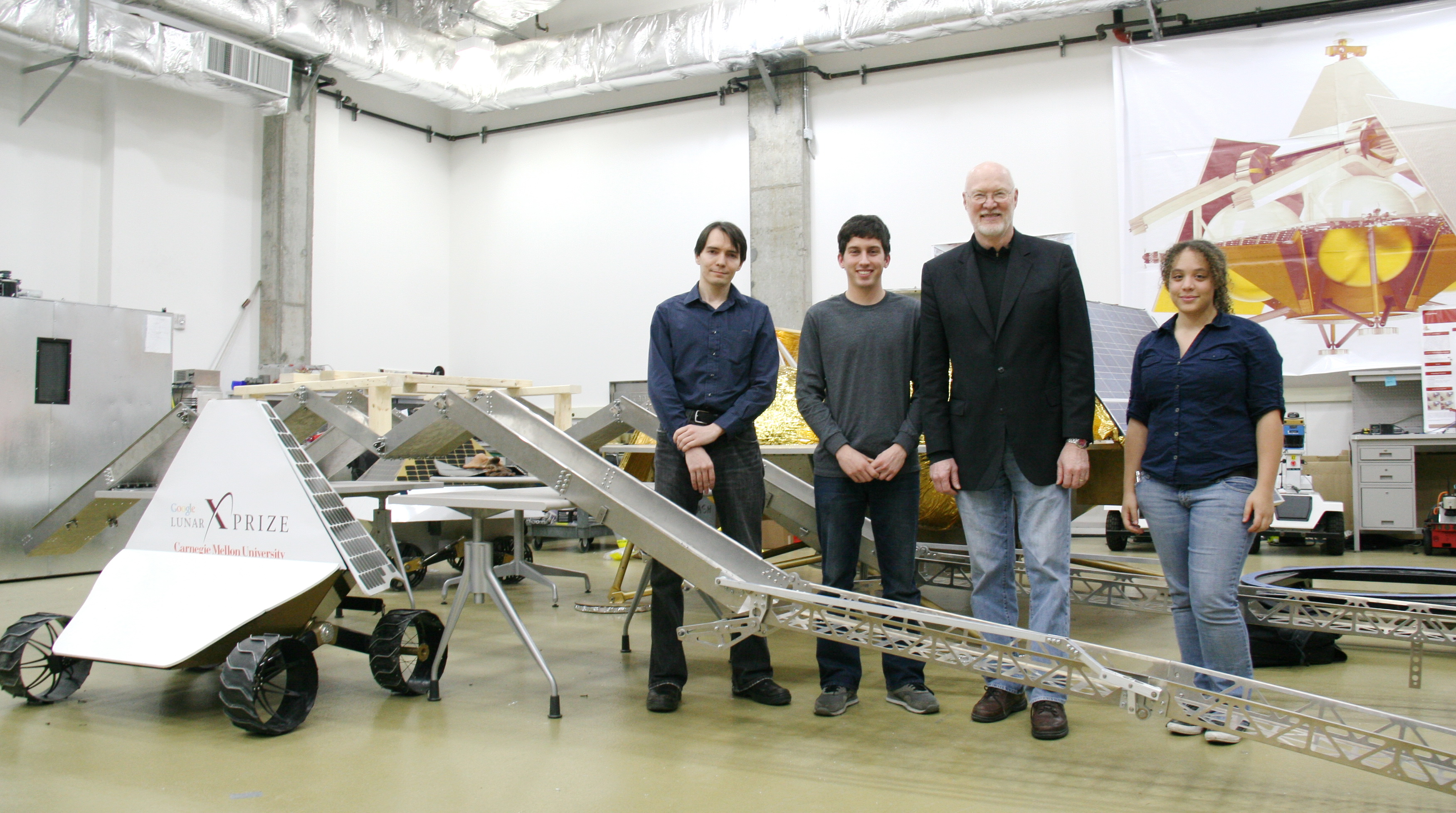
Left to Right: Anton, Zack, Red, Hahna
Our 4th progress presentation was filmed and featured in an
Astrobotic blog post on December 8, 2011. Photos by Allison Jones, Video by Michael Pisano and Jonathan Minard.
The rover egress team presents the design process and fabrication of the lander ramps:
Afterwards, the team finishesd up assembly of the ramps and conducts preliminary deployment tests. The final step is mounting the ramps onto the lander.
The team finishes up assembly:

A closeup of the ramps: