Jump:
 Name
Name -
Team -
Overview -
Feeder -
Dropper -
Neutral Zone -
Electronics -
Software -
Video
This is a reproduction of the original
Team G home page for the CMU Spring 2011 semester Mechatronics course. This website documents the project of the team with a full description of the machine and design process, as well as photos and videos of the machine during development and upon completion.
Our team was one of the teams with the task of creating a device to play a game of Connect Four with an actual, stock-production game board. The system is controlled by two Arduino microcontrollers (a Pro and an Uno) and interfaces with a controlling PC via a standard 9600 baud 8N2 serial connection. A
PDF of the project specifications laid out for us is available.
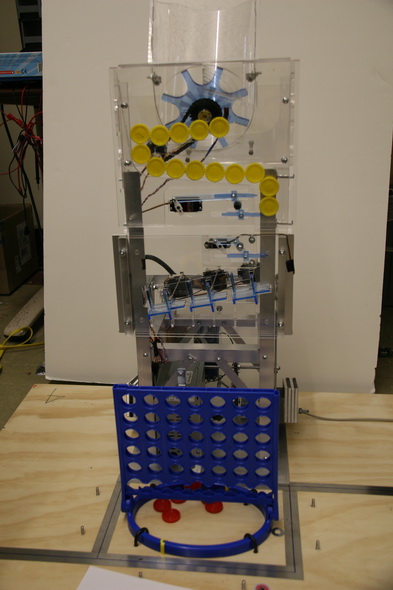
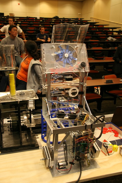
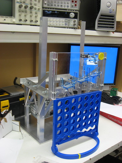
Full System - Front
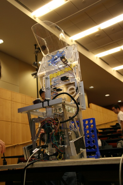
Full System - Rear
Jörmungandr is the 'world-snake' of Norse mythology. The legend goes that Jörmungandr grew large enough that he could encircle the Earth and bite his own tail, as depicted in the background image of this website. Jörmungandr was also responsible for the death of his arch-nemesis, Thor, during Ragnarök. It is said that Thor killed Jörmungandr, then walked nine paces before dropping dead from the serpent's poison.
While the name was originally chosen simply for its exotic appeal, it ended up being quite appropriate for our machine. Starting with the hopper, which is like a snake's rattle, the chips then arrange in the serpentine queue ramp, also much like a snake, before being deployed by our chip dropper. The quick, decisive motion of our chip dropper is not at all unlike the strike of a snake going it for it's poisonous final blow.
Our team is comprised of four students, two of whom come from a mechanical engineering background, and two from an electrical engineering background. Below is a little information on each member, including which portion of this project they primarily focused on.
Jon Daneman is a senior mechanical engineering student. His main area of work for this project was designing and fabricating the chip feeder subsystem, and lots of other CAD work, such as generating animations for progress reports.
Anton Galkin is a graduate mechanical engineering student. His focus was design and fabrication of the chip dropper subsystem, as well as machining and assembly of many components, camerawork (both photo and video), CAD modeling and rendering.
Greg MacLean is a senior electrical & computer & biomedical engineering student. His main area of work for this project has been designing and implementing the game AI that the system uses to play Connect Four. He also did video editing for our final video. In his free time, Greg studies combat strategies to teach Jormungandr how to more effectively defeat Thor.
Warren Pryde is a senior electrical & computer engineering student. For this project, Warren's main work was in implementing the control software to run the actuators and process the sensor inputs. He also handled wiring, sensor/actuator calibration, and system integration, in addition to making the website.
Our central design principal was stability. We strived from the beginning to avoid complicated encoder and feedback schemes for our positioning, instead favoring systems that had physical limitations on their range of motion. This created a system that relied little on extensive calibration to deliver the chips with reasonable reliability. This helped with the cost constraints on the project, allowing us success using the cheaper, class-provided motors and servos without sacrificing accuracy.
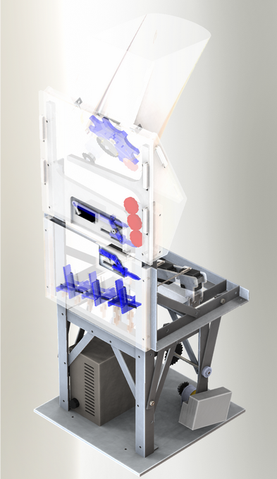
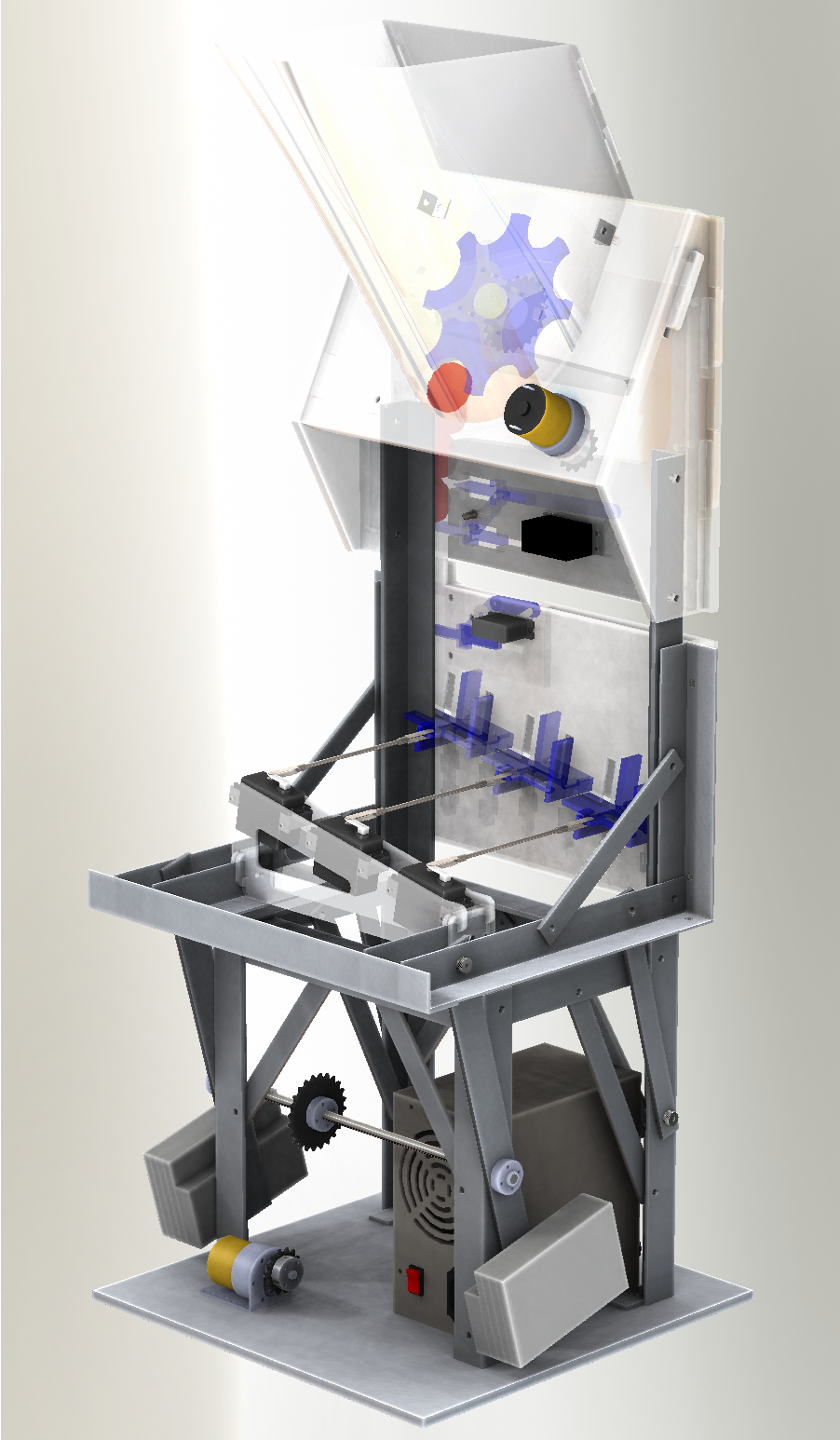
Full System CAD Render - Front

Full System CAD Render - Rear
Our design also involved construction out of lightweight, and aesthetically pleasing laser-cut acrylic, and standard aluminum angle and bar stock, arranged to allow maximum mechanism visibility. We kept our machine footprint small and also kept the total system very lightweight. It can easily be moved by one person. The relative low-cost of these materials allowed us to iterate through design several times when necessary to optimize part fit and geometry. While this was a new medium for our mechanical engineers, they adapted to it quickly, and ended up rather enjoying the simplicity of the medium, which can move quickly from design through fabrication.
The rest of this page will detail the subsystems roughly in the order the chips pass through them, from feeder through deployment into the board, followed by a look at the electronics (including software) behind it all. Diagrams accompany the description of each subsystem. These are simplified for the purpose of exposition of the basic concepts. Actual photos of the device are available on the photo page. We also encourage you to check out the video page to see the mechanisms in action; it makes them much easier to understand.
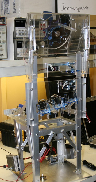
Full System (unfinished) - Front
Full System - Rear
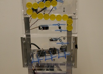
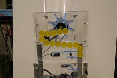
Chips are dropped into the hopper at the top of the machine. When the new game command is issued, the motor running the agitator (Fig. 1) is turned on, which orients the chips properly to enter the queue (Fig. 2). The agitator is turned off once fourteen of the twenty-one chips are queued in the ramp system, and then will be periodically activated again when there is space in the queue for more. If a chip gets jammed in the agitator, a reflectance sensor detects the lack of rotation and will reverse to free the jam with a very high success rate. At the end of the ramp system there is a servo-controlled actuator (Fig. 3) that can release a single chip into the chip dropper below. The servo used for this is a standard analog servo (model Hitec HS-325) with two arms on it. The top arm is extended to prevent the remaining chips in the queue from prematurely falling into the chip dropper, while the bottom arm is withdrawn to allow the bottom chip to pass.
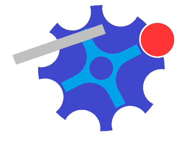
Fig. 1 - Agitator Wheel

Fig. 2 - Queue Ramp
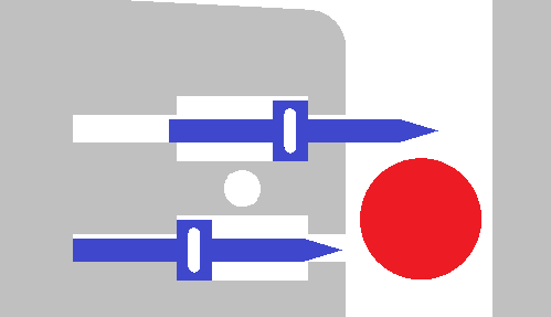
Fig. 3 - Single-Chip Release
Chip Feeder - Version 1
Chip Feeder - Final
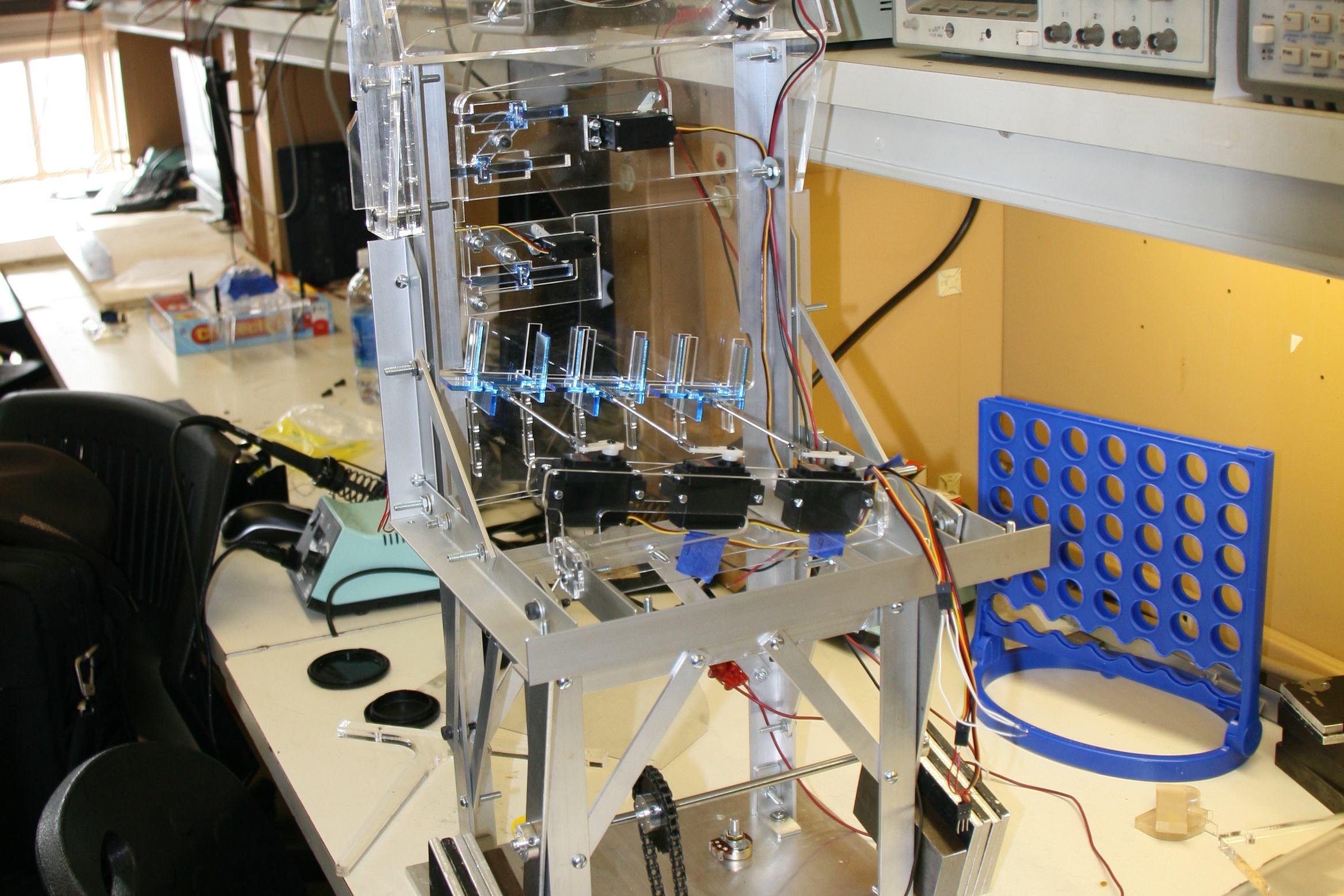
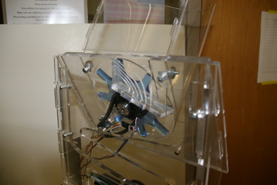
Immediately upon receiving the opponents previous move, a single chip enters the chip dropper (Fig. 4), which is deployed into the neutral zone as described below. The chip dropper begins with a chip release mechanism (Fig. 4 - top right) very similar to the one on the chip feeder, but with only the one arm since there is no need to worry about multiple chips in the dropper (even if somehow more than one was released, there is no room in the mechanism for multiple chips). Once the AI determines the best move, the single chip is released by a micro servo (model Hitec HS-81) into the final ramp (Fig. 4 - bottom two-thirds) where the column selectors deliver it to the proper column. The column is selected by three acrylic assemblies attached to three servos (again, model Hitec HS-325). Each servo controls access to two of the columns, and the last column is always open as a fail-safe. The stability of the system here is ensured by loose tolerances and a physical limitation of motion in one direction. The column-selection servo is activated before the chip is released to make sure that it is in the proper position before the chip reaches it. The chip rolls down the ramps until it reaches the open column, where it falls down into the selected column.
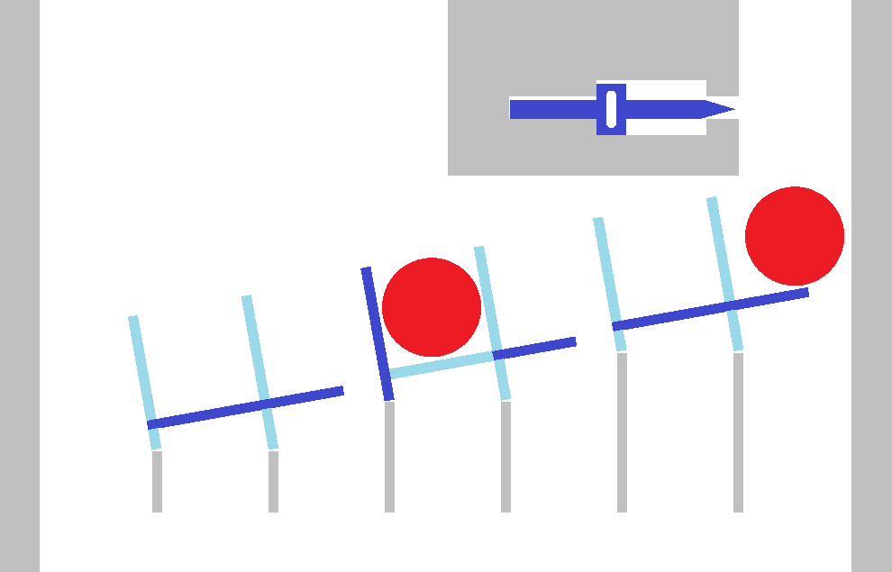
Fig. 4 - Chip Dropper: note chip release mechanism at top,
and column selection mechanisms below.
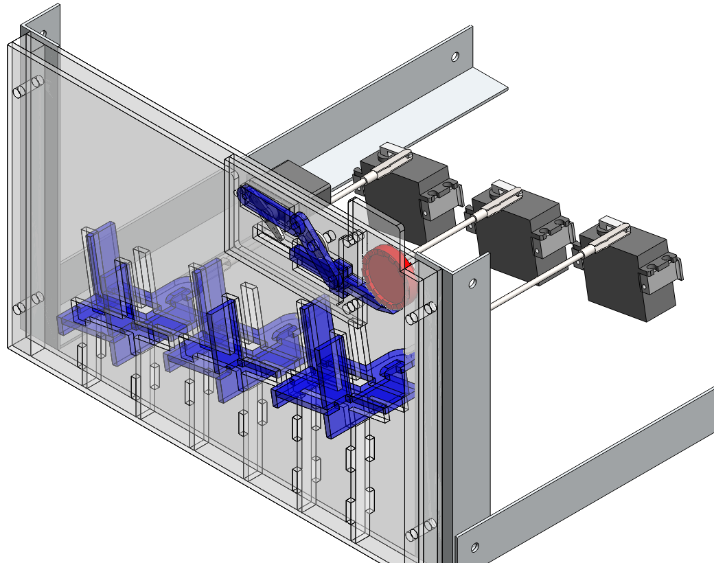
Fig. 5 - Chip Dropper - CAD Render
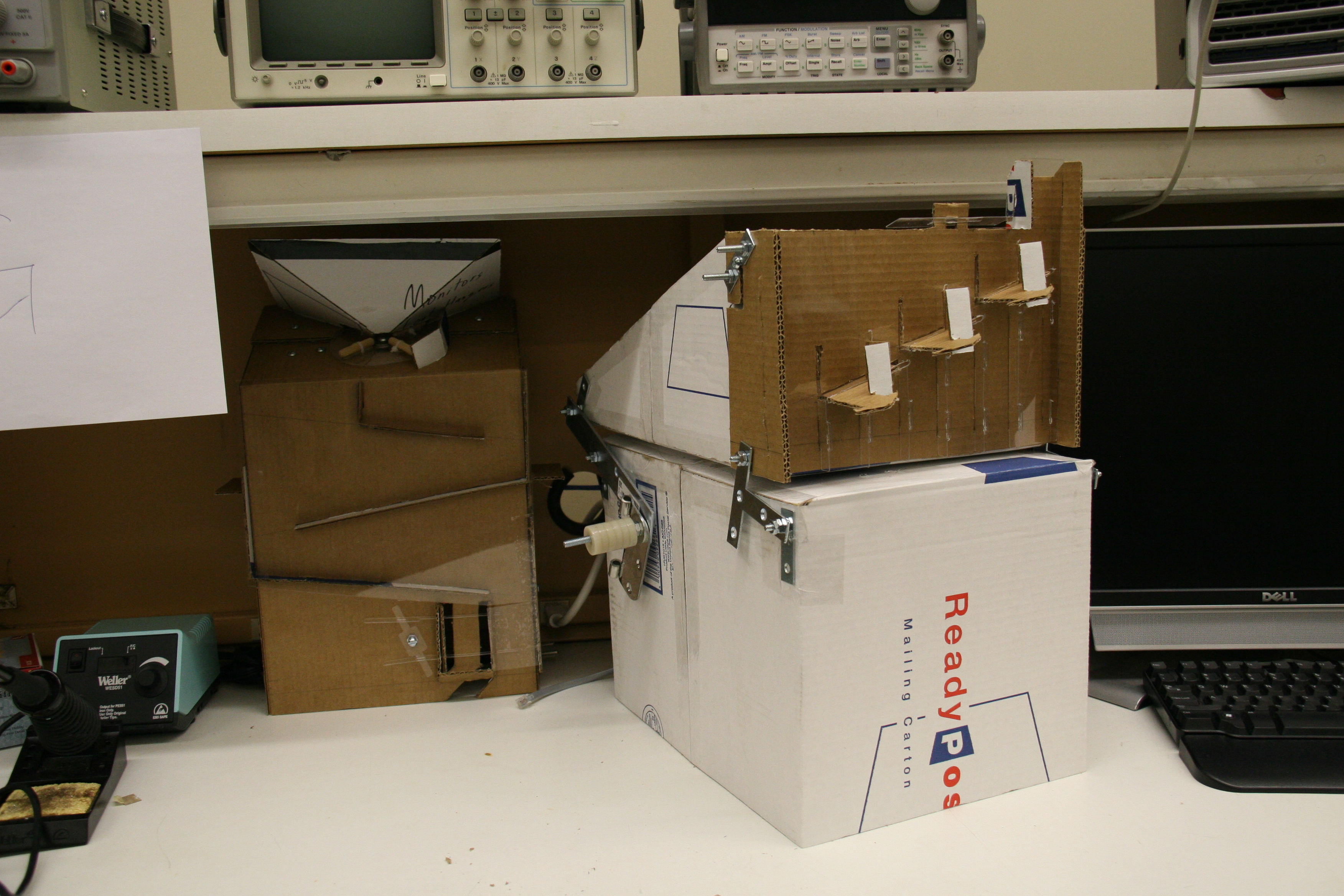
Chip Dropper - Version 1

Chip Dropper - Final
This video shows the original cardboard chip dropper prototype and describes its functions.
This video was taken during a lab session to be used in our mid-semester presentation to the class. It shows the two types of actuation that are used in the chip dropper subsystem. First, it shows one cycle of the subsystem zoomed out. You see the chip begin in the top right of the system, then fall along the ramp, and through the middle chute.Then the video zooms in to show a close-up of the mechanism that releases the chip. Finally, it shows the actuator that selects the column that the chip will fall through.
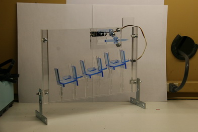
Our neutral zone entry is unique among the teams in the class. Instead of depending on linear actuation, such as a belt, rack and pinion, or lead screw assembly, to reach the column, we enter from behind the board with a four-bar linkage system. Our entire dropper assembly advances into the neutral zone and sits above the game board. This gives us the advantage of a very simple and precise method of positioning the dropper over the board. The alignment is guaranteed because the assembly is at its physical limit in both the extended and retracted states. As long as our base-plate is aligned properly on the studs, the probability of a miss is quite low.
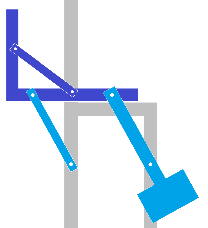
Fig. 6 - Neutral Zone Entry
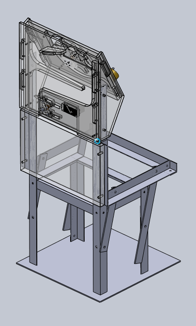
Fig. 7 - Arm Retracted - CAD Render
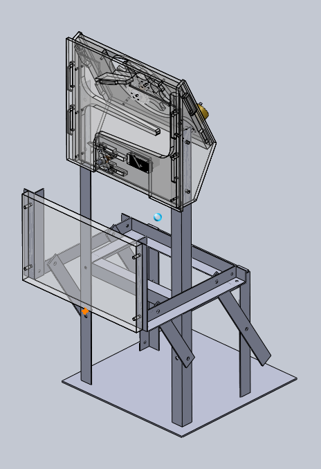
Fig. 8 - Arm Extended - CAD Render

Neutral Zone Entry System - Prototype
Neutral Zone Entry System - Final
This video shows the original cardboard neutral zone entry mechanism prototype and describes its functions.
This video was generated in SolidWorks by Jon from one of the early system mock-ups. It demonstrates how the frame will move the chip dropper from underneath the chip feeder into the neutral zone for gameplay and back. Note that in both positions, the chip dropper ends in a stable position, requiring nothing more than gravity to hold it in place.
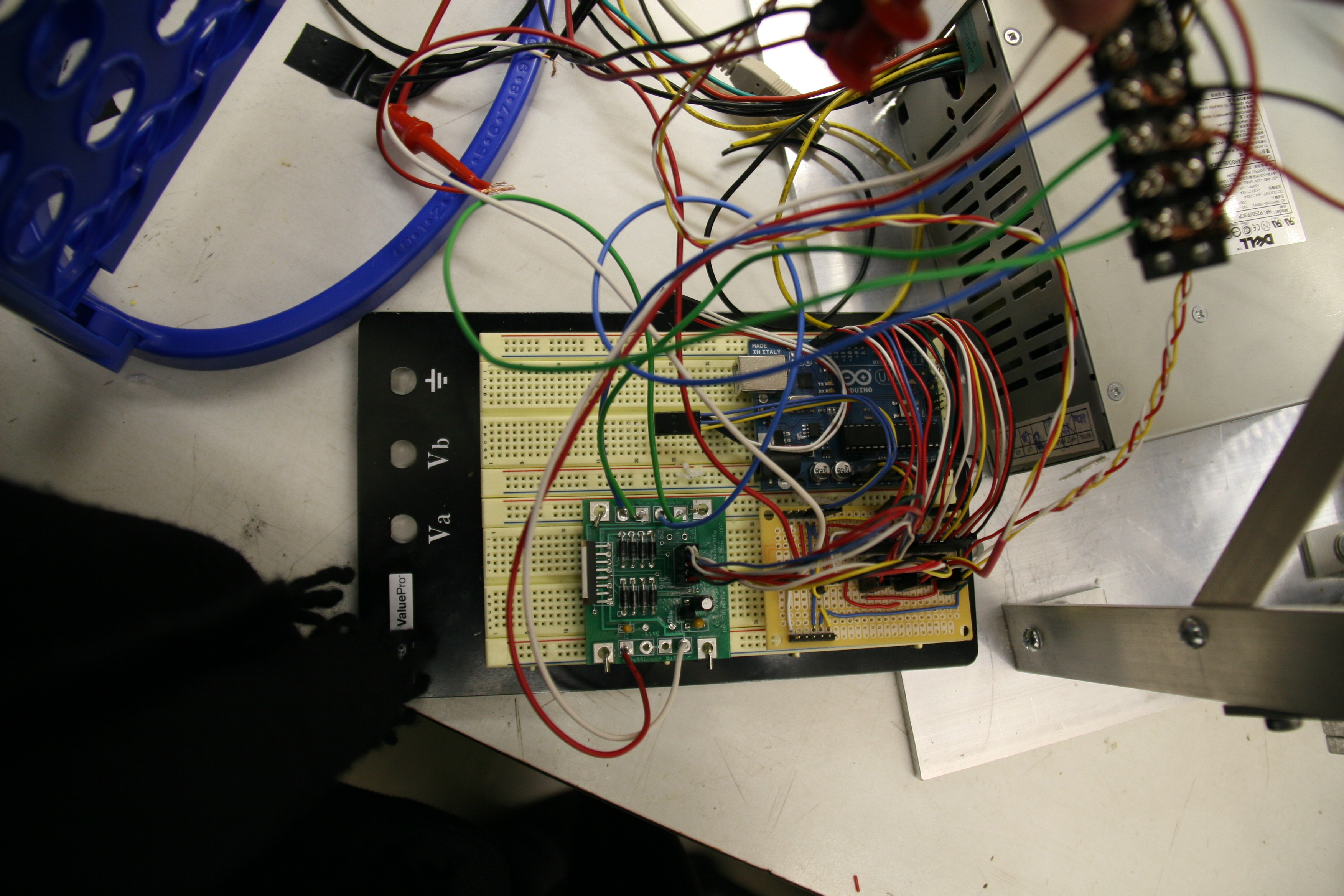
The brain of our machine is two Arduino microcontrollers. First, a Pro runs the AI. Commands come from the controlling PC via serial communication into the Pro, which chooses the next move. Once the move is chosen, the Pro sends the command via a serial connection to an Uno, which carries out the move. While the Uno is awaiting the next move command, it polls the reflectance sensors that detect the presence of chips in the queue and whether the agitator is jammed, and adjusts the agitator accordingly. There are two additional circuit boards involved in the robot: a motor driver board, and a perfboard used for interfacing the microcontrollers and the actuators and sensors. The motor driver board is the type issued by the course, constructed by the team during an early lab session. The interconnect board was constructed by Warren specifically for this project. All sensors and servos are connected to the interconnect board by custom extension cables, with Molex connectors, for modularity. The chip dropper connections all run down a common trunk line, and the other cables are run individually. The motors used for both the neutral zone entry and the agitator are standard JameCo ReliaPro DC motors with gearboxes, issued by the course running with chain drives. Last in the hardware portion of the electronics is the power supply. We used a scavenged 250W Dell ATX computer power supply (Model HP-P2507F3CP), with the extraneous wires trimmed off. We used the 12V and 5V rails, as well as the ground, and the power wire, connected through a rocker switch to ground for powering the machine on and off.
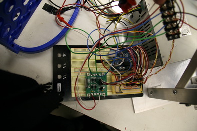
Electrical System - Prototype
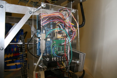
Electrical System - Final
The AI for our machine maintains the game state in memory throughout the game, updating it when it receives the opponent's move, and when it chooses its own move. From the game state, it generates every possible game state for a total of five moves ahead. Once it generates these gameboards (up to 16,807 each turn) it evaluates each one and scores them based on which is most likely to generate a win for us. It executes the next move for whichever game board ranks highest. It also specifically tries to block the situations specified in the project documentation to avoid a loss to the opponent. Some optimization is in place to prevent the machine from trying to consider moves that are invalid (due to the column already being full). The microcontroller's limited resources severely impede the depth to which we can analyze the game. Greg actually developed the AI to look much deeper (tested up to eleven layers deep), but this took too long to execute on the board for the 20 second time limit we have per turn.
The Uno's software is much less complicated. It contains simple routines for manipulating all the servos and motors. Servos are controlled with the Arduino Servo library, which uses one of the internal PWM timers to control up to twelve servo objects with one pin each. Commands given are simply angles for these controls. The center/intial values and movement angles are stored in the Arduino as constants to allow simple recalibration if necessary. The motors are controlled with two digital outputs per motor connected to the motor driver board. The two pins allow the motors to be run forward, backward, or braked. The enable pins are permanently wired high to conserve usage of the limited number of output pins on the Arduino. The motor for the neutral zone entry is simply controlled by timing, with no position encoders necessary to properly operate. On every iteration through the main loop, the Uno software also polls the two reflectance sensors to control the agitator. The Uno keeps track of how many chips have been deployed, and once it is very likely that the hopper is empty, it will turn off the agitator.
Lastly, we will briefly explain our unique communication system. Though we use the prescribed 9600 baud 8N2 encoded serial communication protocol, our exact implementation is unique. It is unique in that instead of bidirectional connections between the different boards and controlling PC, we have a one-way loop through the system. This was to both save output pins, and take advantage of the fact that there is only one buffered serial port on the Arduino boards we used. The communication arrives from the controlling PC to the Pro, which chooses a move and issues commands to the Uno. Once the Uno has carried out the move, it reports the move back to the controlling PC.
This video was created for our public demonstration. It comprises footage of our machine in its final functional form, and shows each subsystem functioning, as well as the total system. Also included is footage of each subsystem from initial cardboard mockups, through CAD models and renders, to the final product.