Jump:
 Operation
 -
Page Shape Study -
Mechanical Design -
Design Process -
Electronics
Bookbot is built to automatically scan entire books without human assistance. Pages are turned robotically, flattened under acrylic plates for image fidelity and captured using a pair of consumer point-and-shoot cameras. The project is funded in part by CMU
RoboClub.
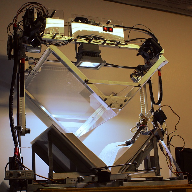
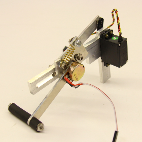
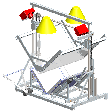
The book is placed in a V-shaped cradle for scanning, to reduce stress on the book's binding compared to a flatbed scanner. A transparent platen is lowered to flatten the pages parallel to the camera sensor plane, reducing geometric distortion. Two cameras capture images of the left and right pages. The platen is raised, and four servos actuate to turn the page: one pair curves the page up by pushing on the corner with high-friction rubber, while another pair inserts a low-friction arm underneath the page to push it over. The process repeats until you have a photo of each page, which can be automatically cropped and processed into a single file using existing software.
The design is inspired by the many which precede it, from
commercial enterprises to
Hobbyists and DIY'ers who work tirelessly to fill the internet with ideas and lessons from their own book-scanner-building experiences.
The actuator design was refined through an experimental study. A 2D simplification is used, assuming books have a prismatic symmetry down the spine.
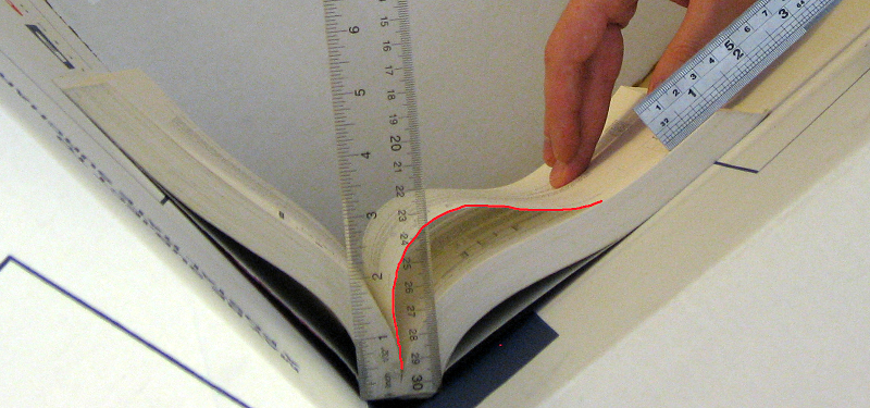
The V-shaped cradle is replicated from cardboard boxes, and book shape is documented as its pages are turned. The operation mimics human page-turning technique, and the sequence is replicated in my actuator design.
Using a MATLAB script, the page shape is extracted and studied to determine optimal actuator dimensions.
The second actuator needs to get under the page after it bulges up, so the goal is to make the opening as large and round as possible. A deflection of 2in is selected for the first actuator, seen here:
The experiment was repeated using different textbooks, with similar results. Thin, softcover books pose a problem for mechanical page turning which will be addressed with future modifications.
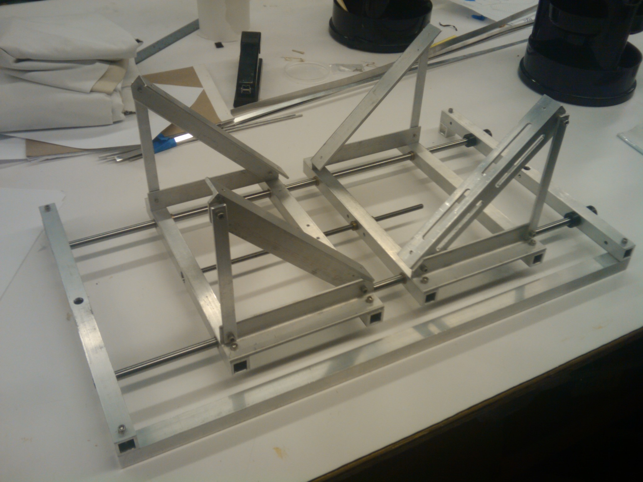
The mechanical components were designed in SolidWorks. High precision and consistent performance are the name of the game when your robot has to work 400 times in a row without human supervision, so aluminum and steel dominate the structure.
While ease of assembly was sacrificed for predictable behavior, all parts were designed for manufacture in a typical machine shop.
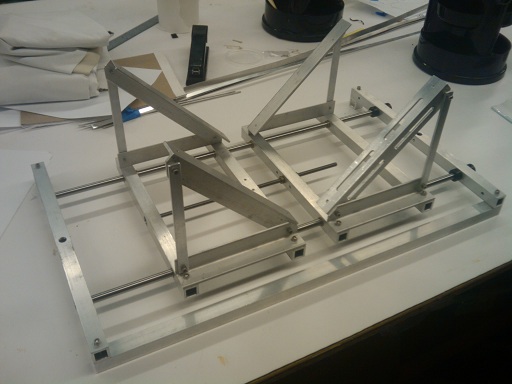
Here, an early stage of construction shows some of the tube structure and linear rails.
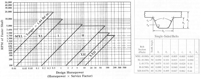
To illustrate the process of getting from concept to machine, consider one component in this complex machine: the timing belt system.
Engineering specifications and calculations dictate the linear motion system used:
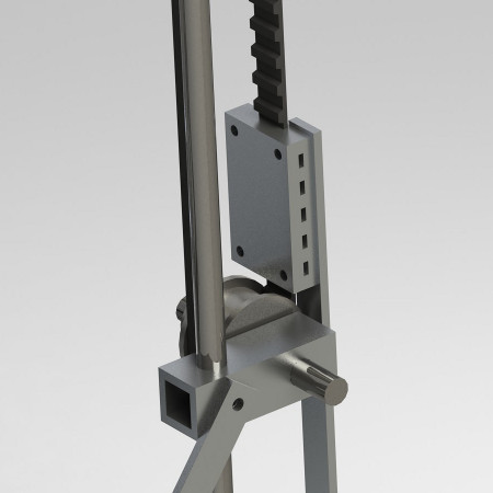
The design is implemented in CAD:
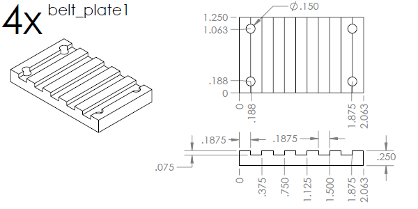
Engineering drawings are created for machining:
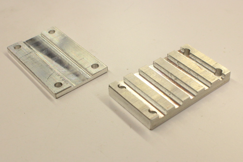
The parts are created in the machine shop:
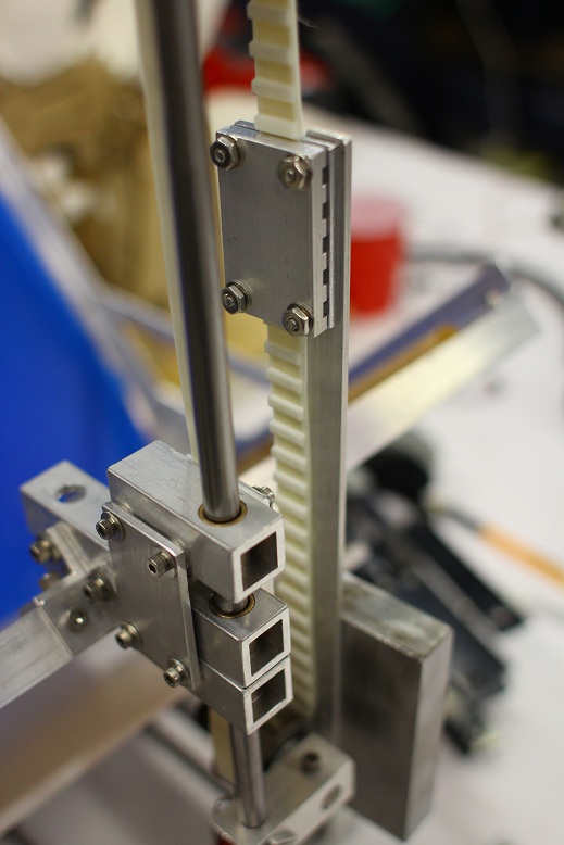
Everything is assembled and fits together perfectly!
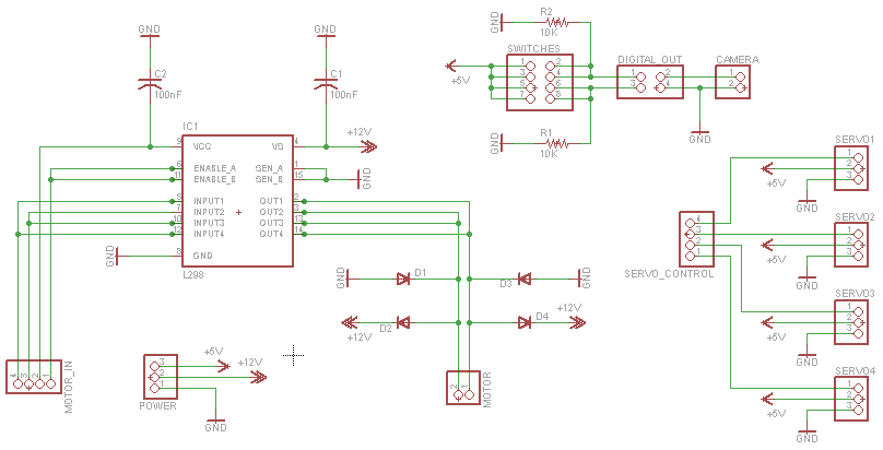
Circuit layed out in EAGLE:
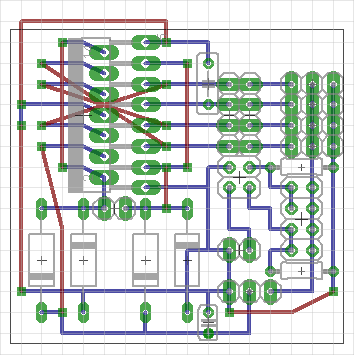
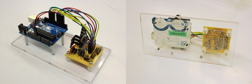
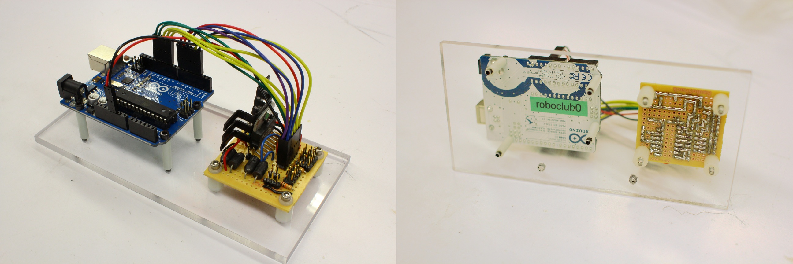
Electronics board connecting Arduino to servos, motor, momentary switches, potentiometer, cameras and power supply:


 This work is licensed under a Creative Commons Attribution-ShareAlike 3.0 Unported License.